Some renders of the BMW E46 model with images uv-mapped onto the paint surface to celebrate the 36th football championship title of Sport Lisboa e Benfica:
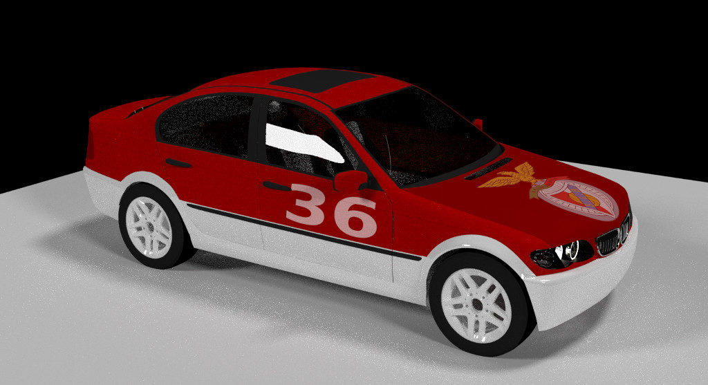
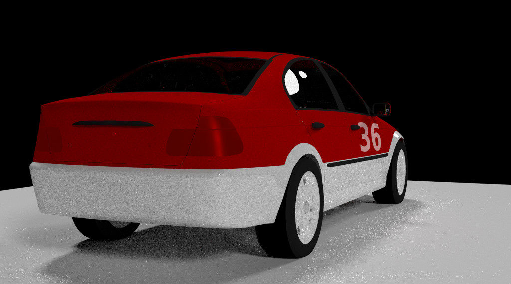
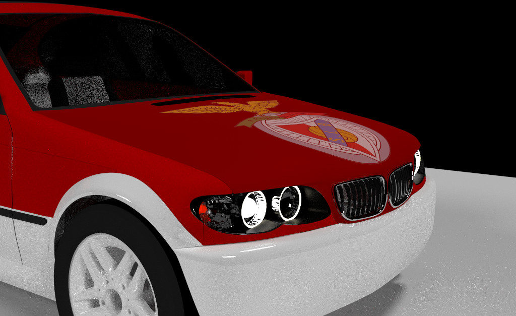
Some renders of the BMW E46 model with images uv-mapped onto the paint surface to celebrate the 36th football championship title of Sport Lisboa e Benfica:
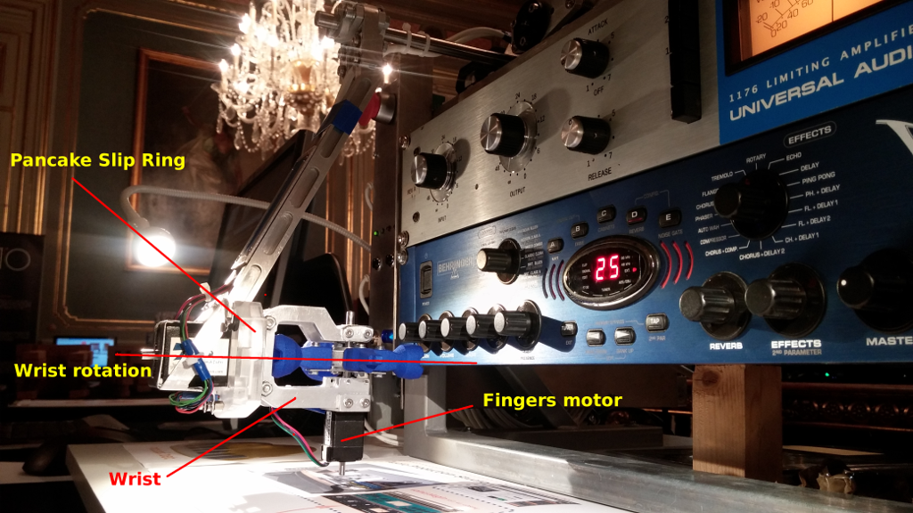
The end effector for the voind robot consists of a “hand” with selectable “fingers” rotating over a “wrist” capable of rotations in excess of 360 degrees. To bridge this rotational gap and transport the 4 signals needed to command the “fingers” motor, I had two options: a) use a flexible cable; b) use a Slip Ring to transmit the four signals.
The first option although simpler had a major drawback: on startup the wrist would have to be manually set in a known position otherwise there would be no way to make sure the wrist would not be commanded to rotate past the point where the flexible cable would start to entangle around the axle.
I then started to look for suitable Pancake Slip Rings but prices were significantly higher than I was prepared to pay for a prototype. So I decided to design and build a slip ring from scratch.
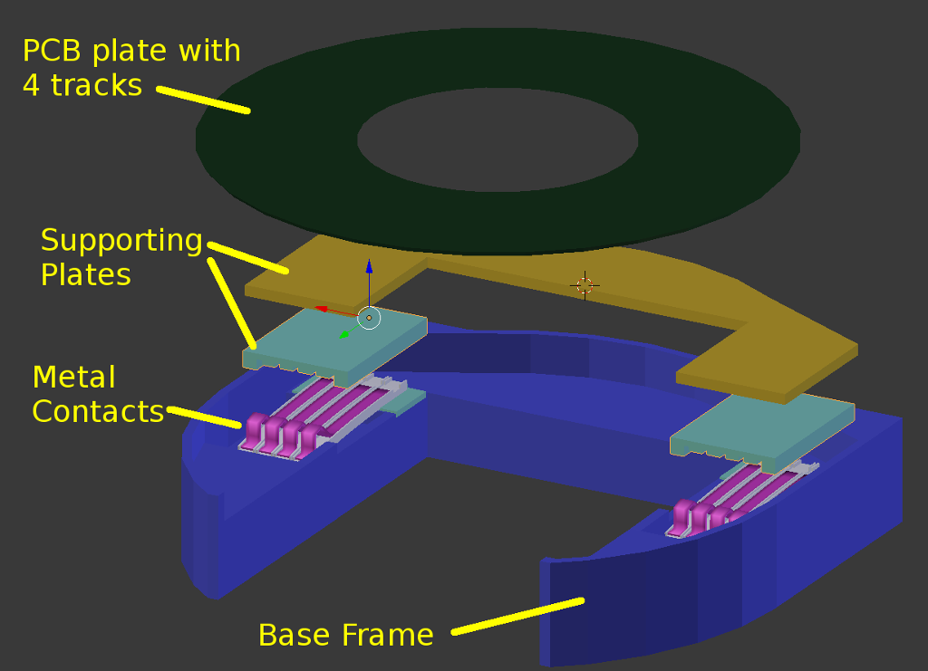
The first step was to create a design that would fit the existing parts. The next figure shows the assembly components. The PCB plate is attached to the “hand” while everything else is part of the “wrist”. The signals are transmitted trough the metal contacts that are touching each of the four concentric tracks on the PCB plate:
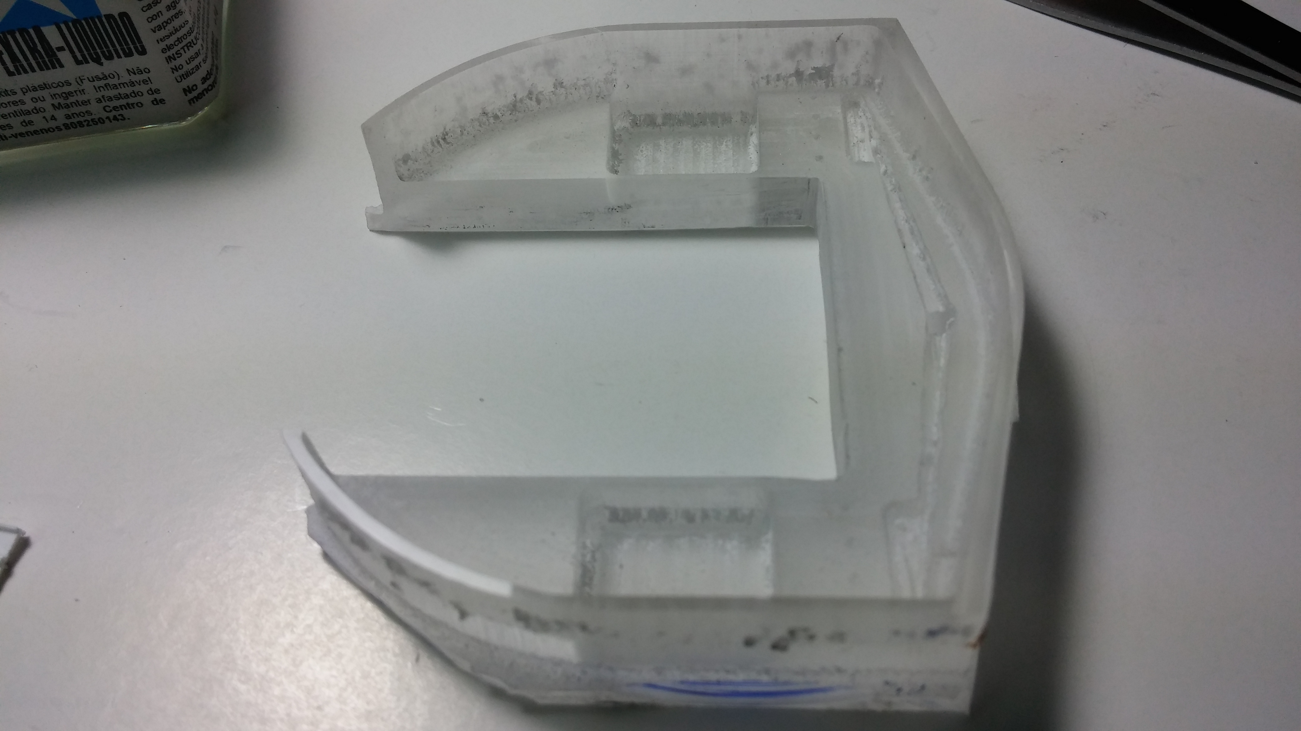
The base frame was fabricated by milling an acrylic plate.
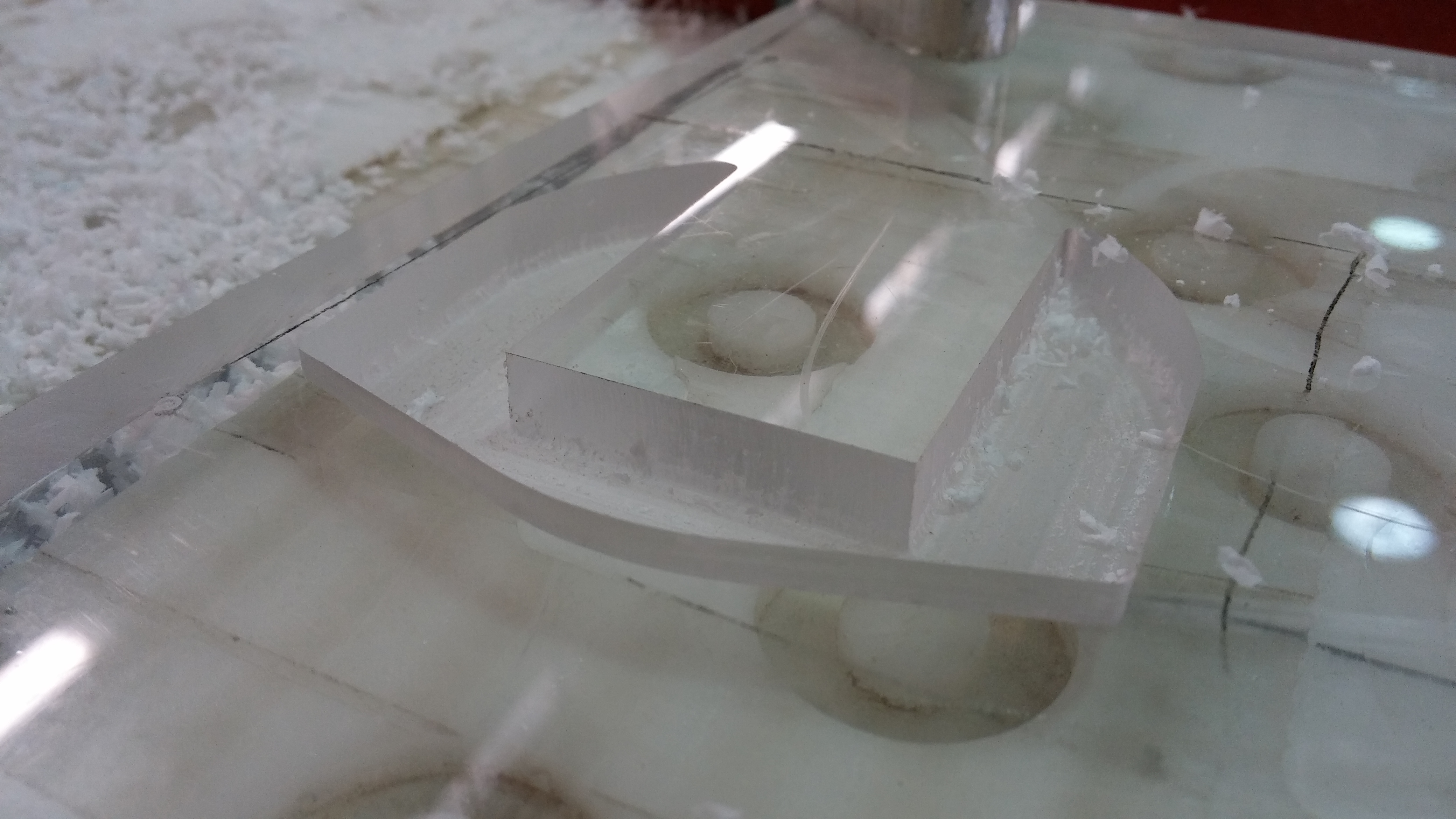
The part before finishing:
The contacts were cut from a sheet of metal salvaged from an old computer:
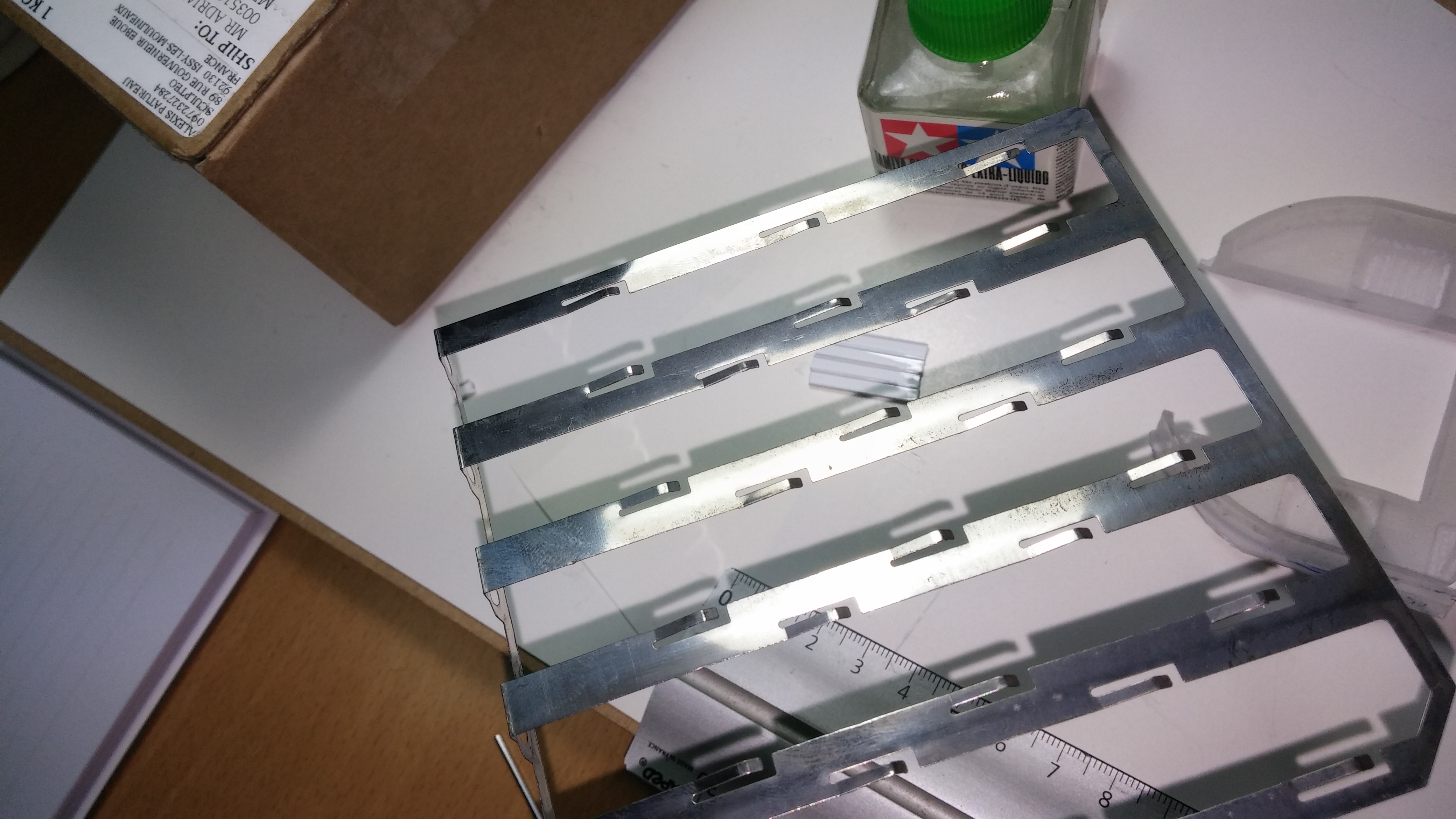
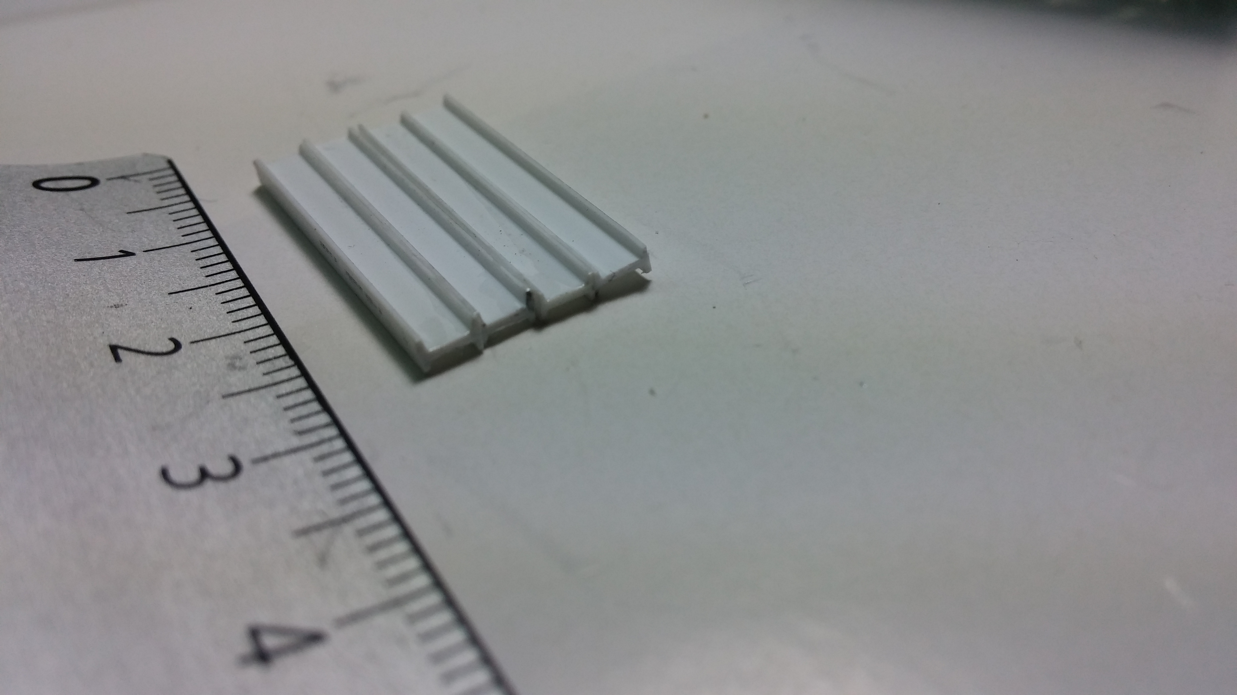
The metal contacts are held in place and separated from each other using small polystyrene profiles normally used for scale models.
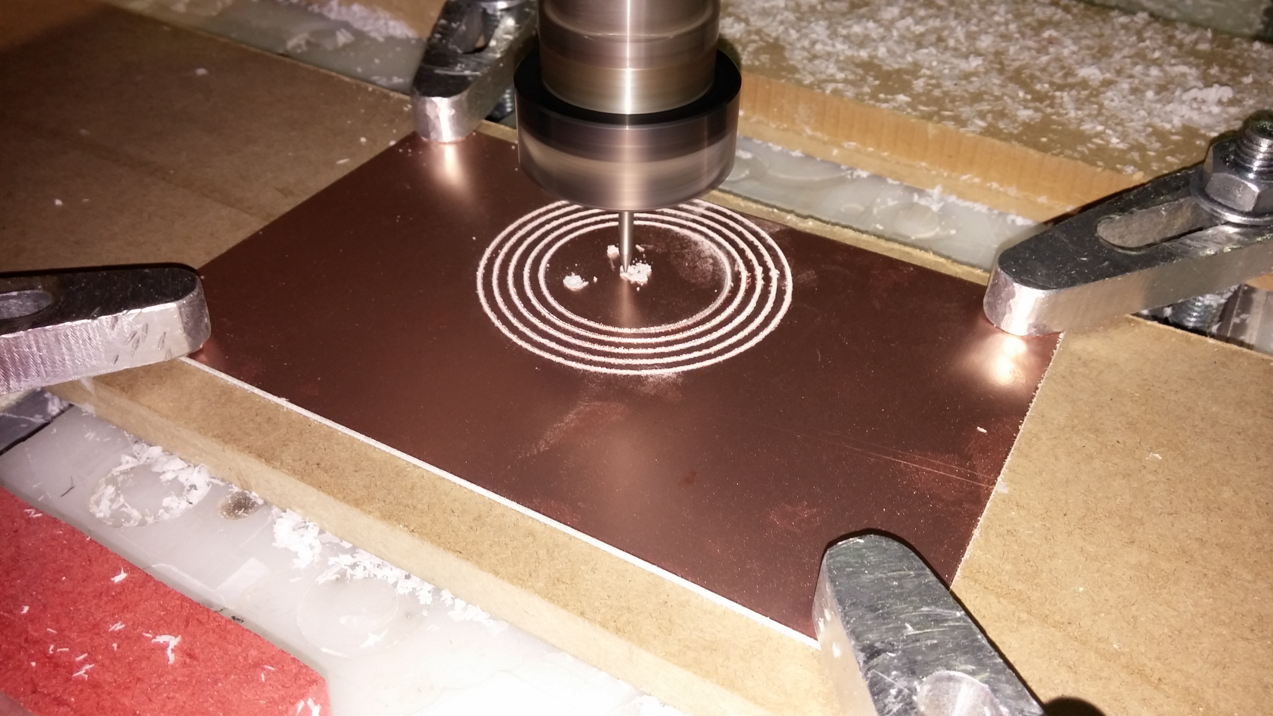
Finally the plate was milled from a standard piece of copper plated PCB:
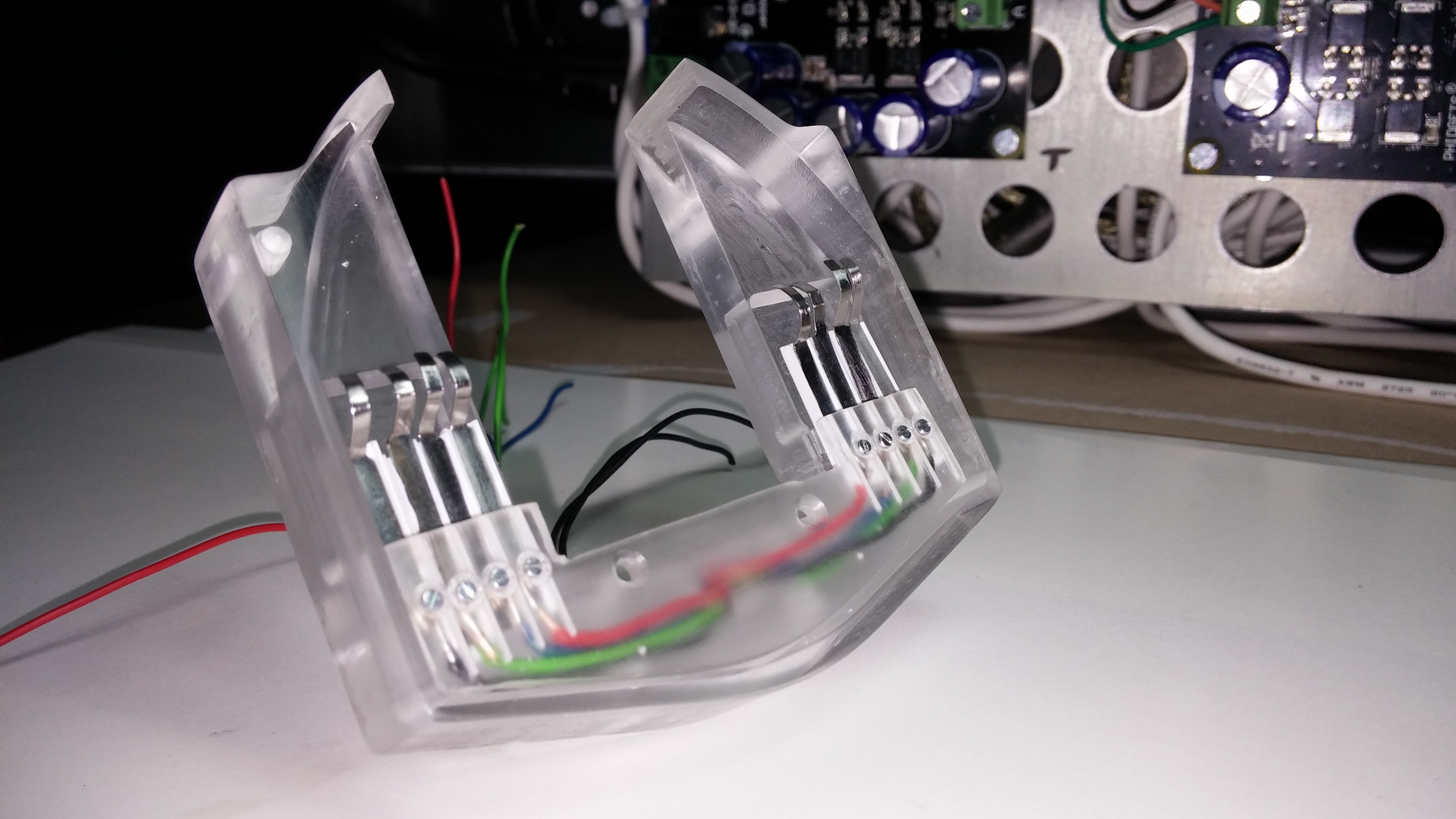
The assembly with the wires already connected and ready to be set against the rotating plate:

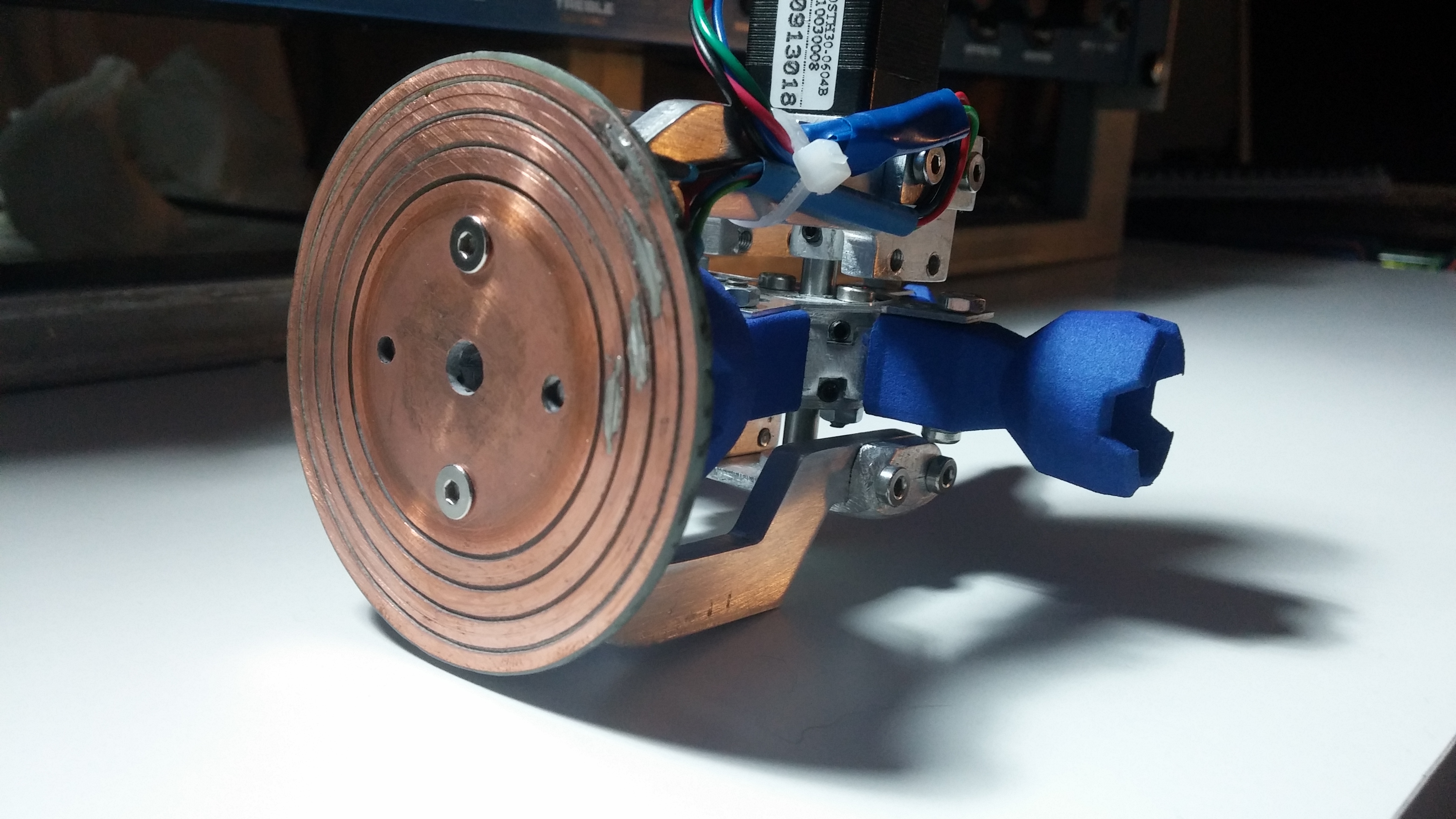
This video shows the first tests using the custom made slip ring:
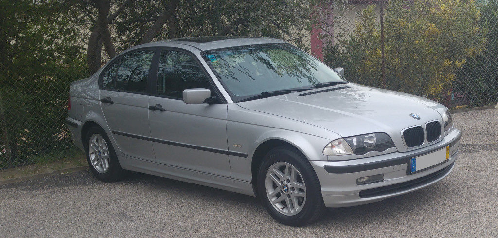
I have replaced the belt vibration damper, belts and tensioner/guide pulleys on my BMW E46 320d. While this is a nearly straightforward operation anyone can perform at home, there are some basic tools and tricks to get the job done properly and safely.
Let me first get this straight! I am no expert in mechanics and you should not take my words as professional advice. I am just curious and eager to share what I learned so far. Do this at your own risk and do not blame me for anything that happens to you or your equipment!
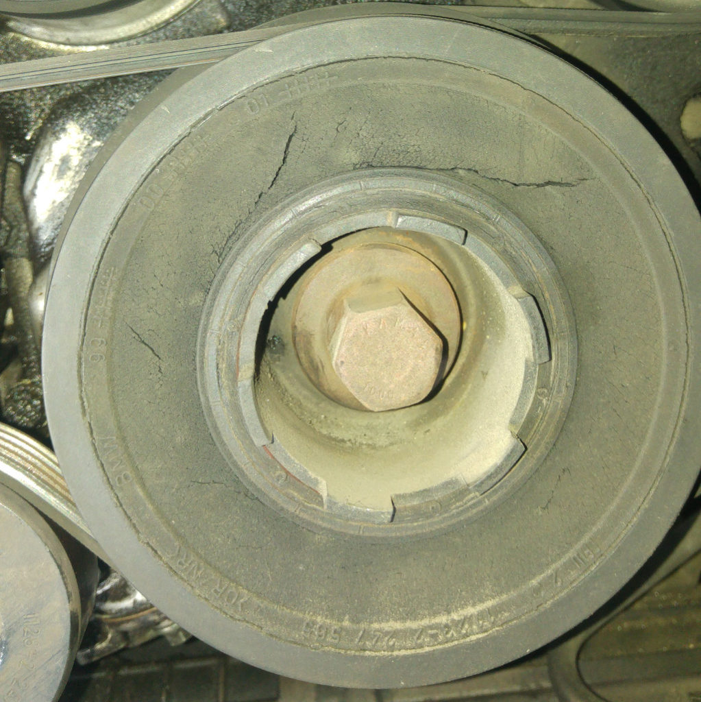
While inspecting my vehicle some weeks ago I noticed some cracks developing on the rubber part of my vibration damper and began linking that to an annoying vibration noise coming from the engine bay, specially at idle. After some investigation it became clear that the damper had to be replaced because I was risking a catastrophic failure not to mention the damage that the vibration might already be causing to the engine.
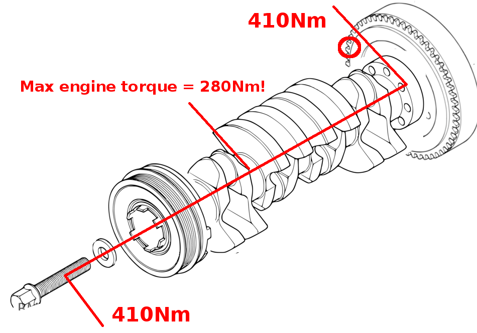
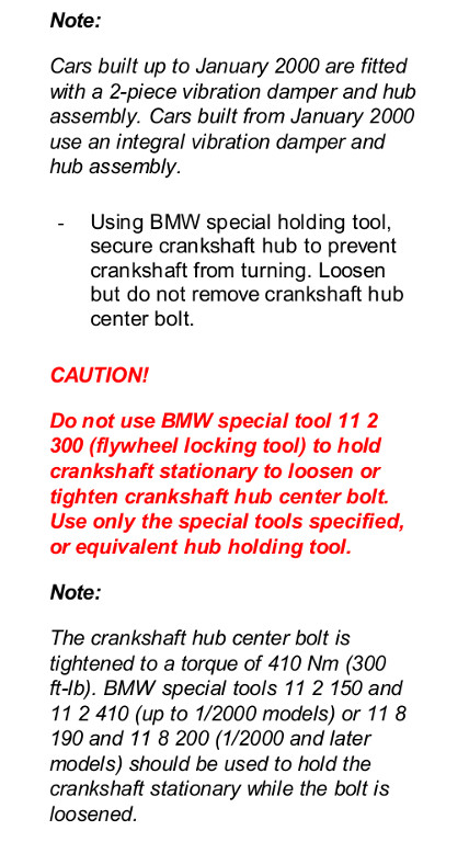
As I was replacing this part it made sense to replace all pulleys and tensioners since these were still the original components that came with the vehicle. Checking the BMW repair manuals I learned that the proper procedure to undo the single bolt that holds the vibration damper is to use a set of special tools to hold the damper in place while applying force to the bolt. Moreover, the torque to apply in order to install the bolt is 410Nm, which is roughly the same as 40Kg on the end of a one-meter long bar!
There are lots of videos on the net showing how to “cleverly” use the starter to undo this bolt, and also how to block the engine flywheel to prevent the crankshaft from turning when applying torque to tighten/unloose the bolt. However none of these tricks seem to be safe and they might ruin your engine! Using the starter with the damper blocked or blocking the flywheel while applying torque to the bolt will cause the torque applied to the crankshaft to largely exceed the maximum engine torque (280Nm). While the crankshaft is designed to support the maximum engine torque, I see no reason why engineers would have designed it to support much more than that, and you will also risk damaging the starter or the gear tooth on the flywheel.
So don’t follow this nor this and do it as per the manual!
As this operation requires a special tool I visited my trusted mechanic to get a quote for labor and parts. While the labor cost seemed reasonable to me, he would not accept for me to bring the parts and would charge me much more for the same parts! To top it off, he would not even consider renting me the special tools I would need to do the operation myself. I totally understand his position as this would completely go against his business model, but this will probably push me further into doing things myself that otherwise I would use his service for.
As a final attempt to source the special tool I made a post on the local BMW user forum asking if someone had the tools for renting – without success.
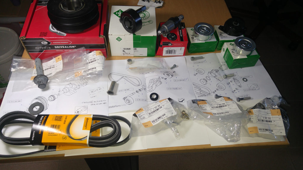
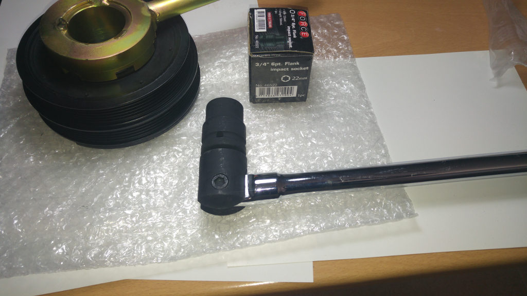
So I ordered the special tool, a 39″ breaker bar and all the parts needed including the vibration damper bolt and washer and all the bolts and bushings I could need to replace.
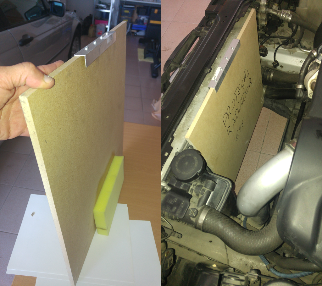
One thing I learned the hard way was how important it is to protect the radiator when you work in close proximity to this fragile component. For that purpose I put together a MDF board with some foam and an aluminum profile to completely protect the radiator from any mishap:
First thing you should do is disconnect the battery to eliminate any chance of accidentally cranking the engine!
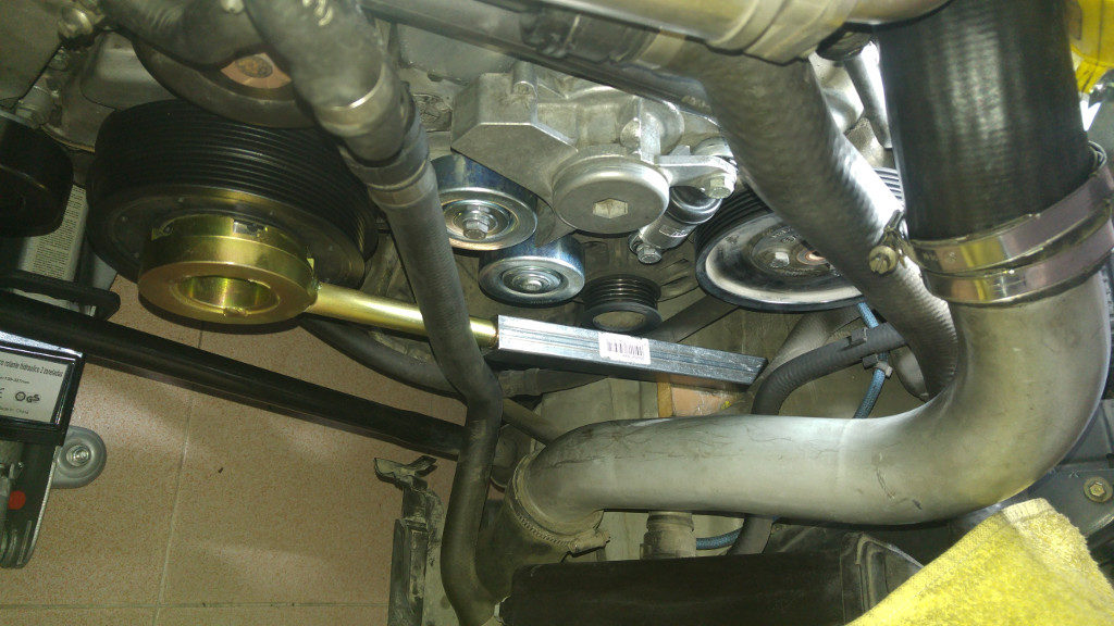
To undo the bolt I set the special tool and a square steel bar against the front tire using a small mdf board to distribute the force:
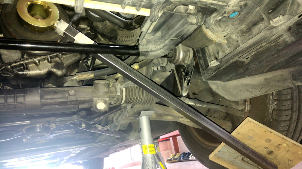
Using the 39″ breaker bar I was able to easily undo the bolt and remove the old the vibration damper.
I was also replacing most of the bolts and bushings but as I tried to remove the two bushings on the the AC compressor supporting bracket, things started to complicate: the old bushings were too tight for easy removal and my attempts to force them out just made everything worse. There was no way I would remove these bushings in place without serious damage to the supporting bracket!
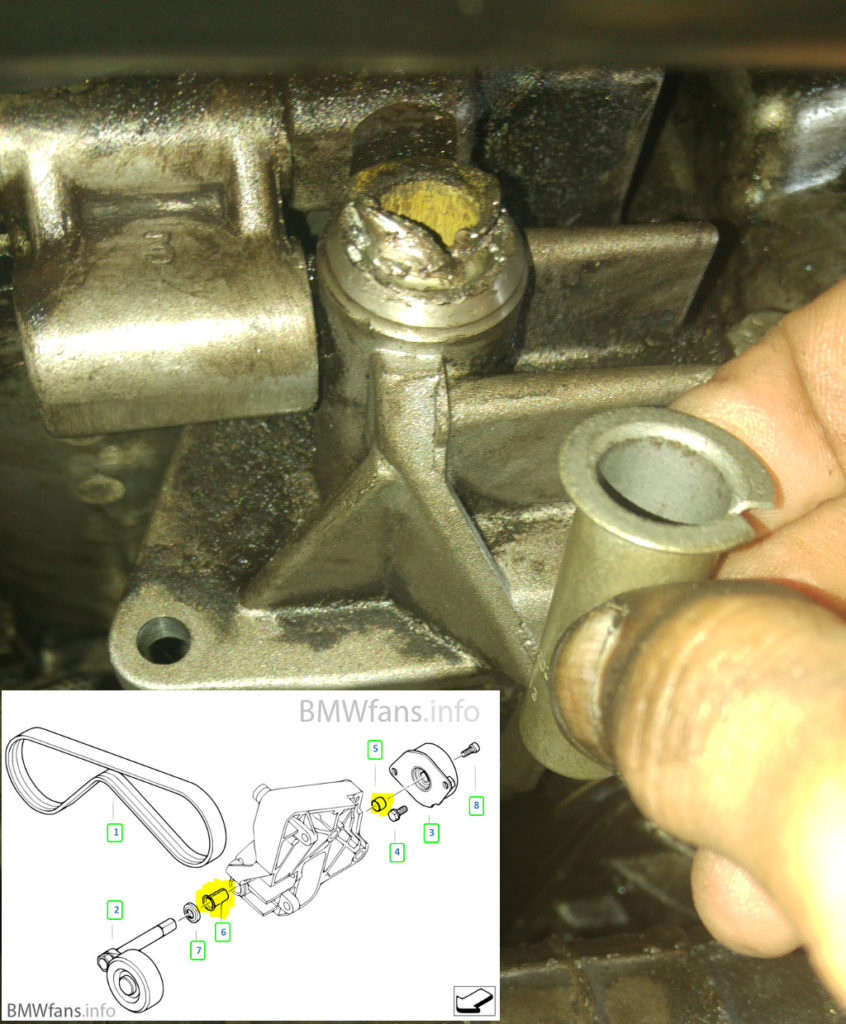
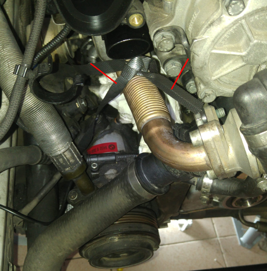
I was considering discharging the AC in order to remove the AC compressor and after that the supporting bracket, but my wise neighbor suggested I should try instead to support the AC compressor and move it slightly aside to be able to remove only the supporting bracket. The following image shows the AC compressor already supported using a plastic strip and hanging from a sturdy exhaust pipe. Note also the air pipe going to the turbo charger already removed and the intake port protected from FOM using a piece of cloth.
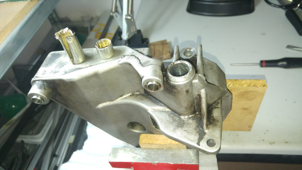
After some fiddling with the screws in the tight space I was able to remove the supporting bracket and then the old bushings. While installing the new bushes it became apparent these are meant to be pressed in and it is next to impossible to remove them while the supporting bracket is mounted on the vehicle .
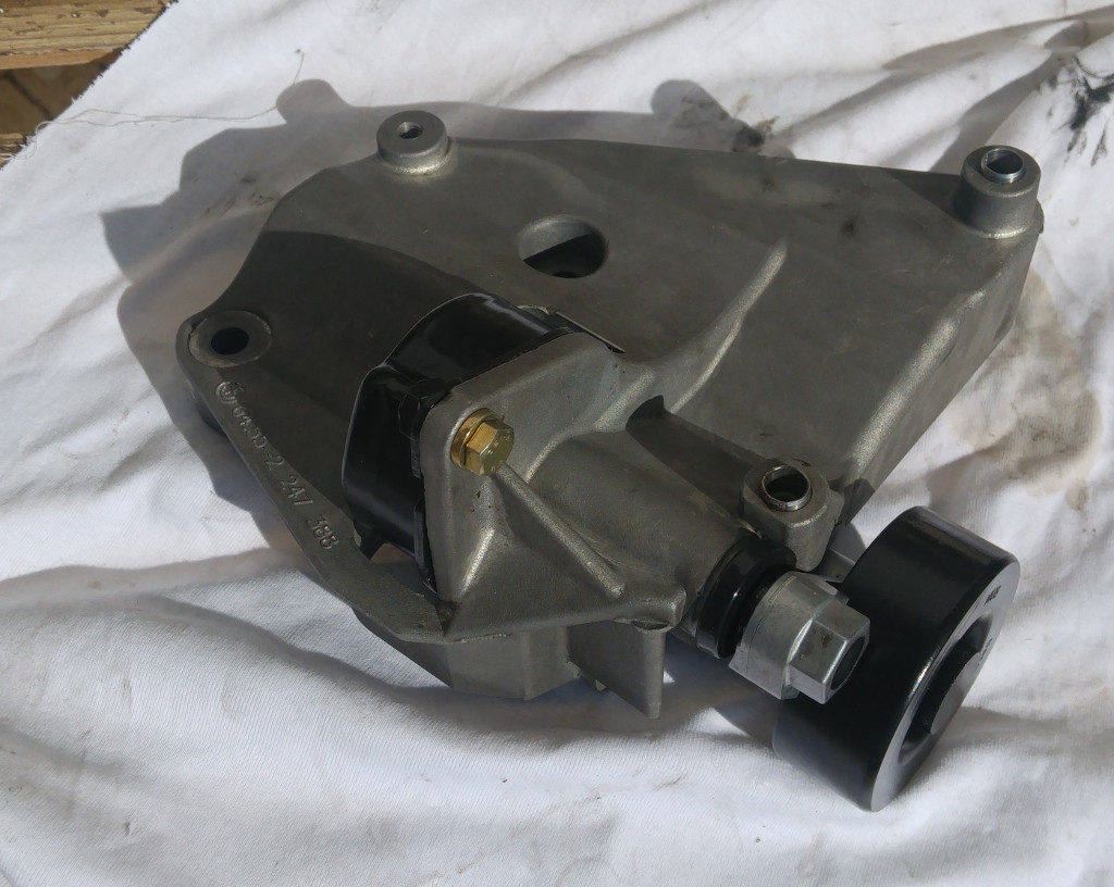
In the next picture the supporting bracket with all the new shinny parts already mounted and ready to be put back in the vehicle:
To tighten the bolt I used the torque specifications on the manual and set the special tool this time against the vehicle framework using a short steel square tube and a mdf block to protect the surface:
After this operation the engine sounds much smoother and gone are most of the vibration and noise that I was already used to… and the car looks better with the new pulleys!
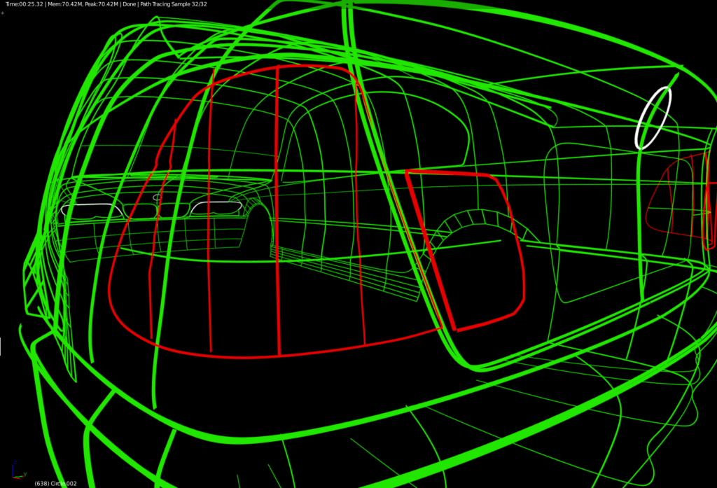
The most important step in creating a realistic 3d model of an existing object is to capture the main lines that define that object in space.
After drawing the main lines in two dimensions over the reference images they must now be “bent” on 3d space to form a convincing representation of the model. It helps to have the real object at hand to check how these lines should look from specific angles, diving into more detail where needed.
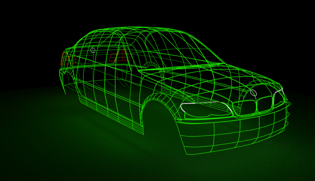
To have a clearer view of how the 3d model looks like I have been using 360/3D renderings visualized using a VR headset. This allows a clearer perception of where the lines stand in space and their relationship to each other.
Please note that the best way to watch this video is using a VR headset and with full 4K resolution. If you watch it on a desktop all you will see is two images (left and right eye) one on top of the other. You can also watch it directly on an Android device but you will be loosing the 3D part of the experience.
Enjoy!
I have been trying to make some 360 VR animations of scenes on earth orbit and for that my starting point has been this excellent How to Create a Realistic Earth in Blender tutorial.
However, to render for 360 in Blender the camera has to be set to Panoramic Equirectangular, and that means that Cycles render engine must be used.
This article describes how I managed to get one of the basic requirements for a realistic earth rendering which is making the clouds cast shadows over the terrain.
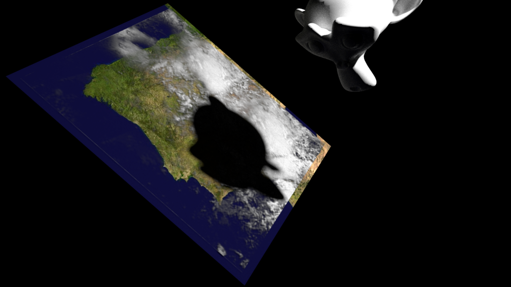
I started by setting up a simple scene with two planes illuminated by a distant sphere with an emitting material (the white sphere on the top). The two planes represent the terrain and the cloud cover separated by a very small gap.

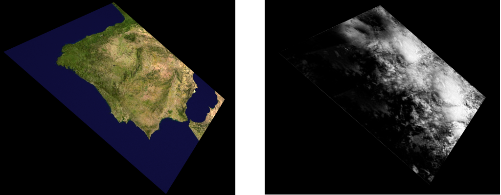
I used two high resolution images to texture each of the planes:

Separate renders of both terrain and cloud layers:
Rendering with both layers. The shadows cast by clouds over the terrain are clearly visible.

This was done using the following settings for the Terrain and Clouds materials:
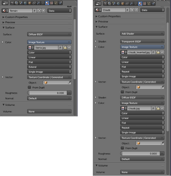
Please note that an additional clouds_inverted.jpg image is used. This is an inverted image of the clouds.jpg image to drive the transparency of the cloud layer: high (white) areas on the cloud cover are transformed into low values driving reduced transparency and projecting shadows over the terrain.
Next step will be modeling how a giant Suzanne will look like from orbit…